
![]()
This sequence illustrates the installation of the differential controller and sensor wiring. The differential controller is the brains of the solar system. It works in conjunction with two sensors, one located at the coldest part of the system - the bottom of the tank - and one located at the hottest part of the system - at the collector outlet. When the sensors register that there is a large enough temperature difference between the two sensors (usually 15-20° F), the controller in turn registers this and activates the pump. When the temperature difference drops to about 3-5° F, the pump is turned off.
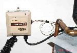 |
Differential controllers come with LED displays, digital readouts, and a variety of options. This differential controller is installed in the vicinity of the water heater. |
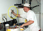 |
Since the controller and pump need 110V AC power to operate, a receptacle must be close by. The controller can be mounted to the wall or even to the water heater. |
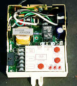 |
The controller is an electronic device that basically interprets the electrical measurements coming from the tank and collector sensors. |
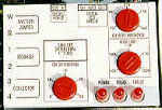 |
The controller has several manual settings. These include the "on" differential setting, high temperature setting, and "off" setting. LED lights located at the bottom right provide operation indicators. |
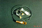 |
The sensors come separate from the sensor wiring. In this case this sensor "kit" provides the sensors, mounting clamps, sensor wire connectors and thermal paste. |
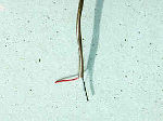 |
Sensor wiring is used for the long wiring runs between the controller and the tank and collector sensor. This wiring must also be protected from environmental conditions if it is exposed to outdoor conditions. |
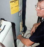 |
After mounting the controller, the installer then attaches the "cold" sensor to a location at the bottom of the tank. Care must be taken to ensure that the sensor makes good contact with the tank wall or the bottom piping. |
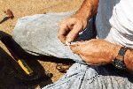 |
The installer then begins the process of attaching the "hot" sensor to the collector outlet piping. Here, he is affixing thermal paste which will provide a good contact between the sensor and the piping. |
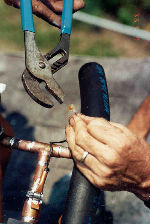 |
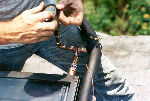
The installer attaches the sensor to the collector outlet piping with a stainless steel hose clamp. Note that he has installed the sensor close to the outlet of the collector. This will register the hottest temperature. The sensor lead wire (also called the sensor pig tail) is then attached to the sensor wire using a silicon imbedded wire connector. |
 |
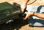
The sensor wire run is then mechanically secured so that it is not loose. |
 |
This is followed by covering the sensor with piping insulation. |
