
![]()
One of the the first question most homeowners ask when considering a solar system, is how it will affect their roof. In other words, is there a possibility that there could be leaks. When the collector, and more importantly, the roof piping penetrations are done correctly, there will be no leaks through these penetrations. Following is a step-by-step chronicle of the proper way to flash and seal roof piping penetrations.
 |
First, the installer identifies and marks the locations of the roof piping penetrations. There will be two penetrations, one for the collector feed line and another for the collector return line. |
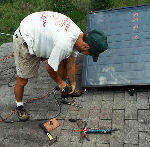 |
Using a wood drill, the installer drills a hole through the shingle and the roof sheathing. This will be used for the collector feed line. The collector feed penetration is below the bottom of the collector. This will allow the collector to be drained for future maintenance or service. |
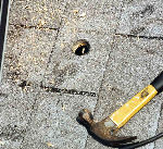 |
Note that the hole drilled for the collector feed line is located in the center of the shingle. This will become important during the installation of the copper flashing. The size of the hole corresponds to the diameter of the copper piping that will be used. |
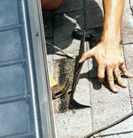 |
Using the proper tools, the installer gently lifts the shingle containing the penetration hole. Special care has to be taken not to rip or split the shingle while lifting it up. In Florida, shingles are commonly used on roofs. In the event tiles are used, the installation method would be quite different. |
 |
Continuing with the work, the installer then affixes a protective sealant to the bottom of the copper flashing. Care must be taken to use a sealant that does not degrade or loose its sealant characteristics. |
 |
The copper flashing is then carefully placed underneath the shingle. The collar on the flashing is gently inserted through the hole in the shingle. Since the hole was made in the center of the shingle, the sides of the flashing will be underneath the shingle. This provides a very professional and clean looking installation. |
 |
The installer then presses the shingle over the flashing and the flashing collar. A little force spreads the sealant material that was put on the underside of the flashing. The following photographs show a close-up of the copper flashing used in solar system installations. |
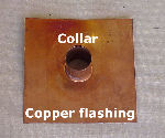 |
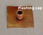
This illustration shows a close up of the copper flashing and the flashing collar through which the piping will be inserted. In most cases, the copper flashing is 4-6" wide. This provides sufficient area to fit securely under the shingles. |
 |
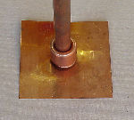
The copper flashing is shown with the flashing cap installed over the collar. The copper tubing from the attic will be fed through the flashing collar and cap. The flashing cap is for systems using copper piping. |
 |
This photograph indicates how the copper piping is fed through the flashing collar and the flashing cap. The piping will be soldered to the top of the flashing cap. In this manner, the piping and flashing cap can ride up and down the collar whenever the piping expands or contracts due to temperature fluctuations. |
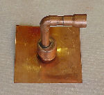 |
This photograph shows the collector feed (or return) piping soldered to the flashing cap. From there, ancillary system fittings are soldered to the piping for further installation of other system piping or valves. |
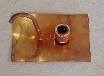 |
For those systems that use sensor wiring, a special fitting (thin, bent copper pipe at left) is included in the flashing cap for the sensor routing. In this manner, the penetration for the sensor wire is also well sealed. |
